电光火石
今天(5月6号)电机学课上,老师正在讲交流电机绕组。
笔者参与开发的电机设计优化软件中,绕组连接图模块还是沉疴未除。
前几个月里,这一部分的debug工作因为各种原因被搁置。
不知不觉间,创意的火花被点燃,“重构这个模块”的想法出现在我脑海里。
前情提要
在商业电机设计软件中,绕组分析模块绕组链接图效果是这样的。
笔者此前的绕组绘制模块主要参考了 陈嘉豪 在 ACMOP 中的绕组分析部分。
ACMOP(Alternating Current Machine Optimization Project),是一个比较完善的电机设计优化项目。在绕组模块,陈主要使用了 python 的 pycairo 库,提供了包括槽电势星型图、绕组链接图等等全流程的绕组分析。
总体评价,陈是笔者暂时无法企及的大佬。但是,针对笔者需求,陈的模块存在一些问题。
1.在笔者的项目中,只需要绘制一张绕组连接图,但是 ACMOP 提供的绕组分析工具太繁复,太“重”。
2.ACMOP 在一些细节上存在问题,如绘制单层绕组(下图)。
3.作为一个有追求的 Coder,笔者觉得 ACMOP 这一部分的代码逻辑走了一些弯路。陷入很多不必要的分类讨论和判断。尤其是画布边缘的端部绕组连接,这一部分在下面介绍笔者的思路时候会详细阐述。
由于思路的形成已经在好久之前,笔者懒得一点一点翻 ACMOP 的代码了,读者可以参考陈在b站上的思路讲解,自行体会。ACMOP-番外1:绕组接线图之Python自动绘制 | 矢量制图库pycairo-哔哩哔哩 Hurry Chen大佬还是很厉害的。
漏掉的电机学知识&一些程序技巧
漏掉的电机学知识。。。
那就漏掉吧(bushi)。
这一part主要讲讲在用程序实现绘制绕组链接图中的几个比较重要的想法。
初始化和它的自变量s
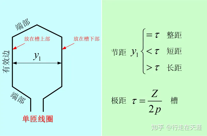
- Z 定子槽数
- tou 极距
- y1 节距
- n 绕组层数 单层/双层
- a 并联支路数
- N 绕组匝数 单匝/双匝
过程中,笔者计算得出每极每相槽数(Number of slots per pole per phase),记为 spppp。(虽然可能 s4p 会简洁一点,但是笔者喜欢 spppp 这个略带喜感的变量名)
值得注意的是,其中并没有极对数、电角度这些重要电机参数。其实笔者变量的选择是有考量的。 出于模块化和明确接口的想法,绕组绘制模块只接收与绕组绘制直接相关的参数。
class winding(object):
    def __init__(self,Z,tou,y1,n,a,N):
        self.Z,self.tou,self.y1,self.n,self.a,self.drawAllPhase=Z,tou,y1,n,a,drawAllPhase

        self.multiTurn=0
        if N>1:
            self.multiTurn=1    # 多匝绕组

        self.colorMap=["r","g","b",]# A-r B-b C-g
        self.layerBias=0.1  # 两层绕组的偏移=2*self.layerBias
        self.terminalBias=0.1 # 端部引出线的偏移

        self.h1=2   # 有效边下侧的y值
        self.h3=8   # 有效边上侧的y值
        self.h2=(self.h1+self.h3)/2   # 序号标签的y值
        self.deltaH=(self.h3-self.h1)/2
        self.h0=self.h1- self.deltaH  # 下侧端部最底值的y值
        self.h4=self.h3+ self.deltaH   # 上侧端部最高值的y值

        self.fig = plt.figure(figsize=(8,3),dpi=200)
从线圈到线条
众所周知,绕组连接图可以看做若干个单匝线圈(或者多匝线圈)连接而成。
考虑到单匝线圈感应出的电动势明显小于多匝线圈,且实际应用中多匝线圈的电机使用更多,为了省事,笔者在程序中虽然考虑了线圈匝数但是,基本上按照多匝线圈的画法去绘制。
def drawVerticalLine(self,x,phase,layer):
        """
        画绕组连接图有效部分:画一条垂直线
        """
        color=self.colorMap[phase]
        linestyle=[‘-‘,‘--‘][layer] # 第一层为实线,第二层为虚线
        plt.plot([x,x],[self.h1,self.h3],color=color,linestyle=linestyle)

    def drawFoldingLineUpper(self,x1,x2,phase,layer):
        """
        画绕组端部(上方)
        """
        color=self.colorMap[phase]
        xmid=(x1+x2)/2
        linestyle=‘-‘
        plt.plot([x1,xmid],[self.h3,self.h4],color=color,linestyle=linestyle)   # 左侧边
        linestyle=[‘-‘,‘--‘][layer] # 第一层为实线,第二层为虚线
        plt.plot([xmid,x2],[self.h4,self.h3],color=color,linestyle=linestyle)   # 右侧边

    def drawFoldingLineLower(self,x1,x2,phase,layer):
        """
        画绕组端部(下方)
        """
        color=self.colorMap[phase]
        xmid=(x1+x2)/2
        linestyle=‘-‘
        plt.plot([x1,xmid],[self.h1,self.h0],color=color,linestyle=linestyle)   # 左侧边
        linestyle=[‘-‘,‘--‘][layer] # 第一层为实线,第二层为虚线
        plt.plot([xmid,x2],[self.h0,self.h1],color=color,linestyle=linestyle)   # 右侧边
一些纯粹的工具函数,一个函数只干一件事与可复用性结合。
循环,计数,绘图
def draw(self):
        spppp=self.tou/3    #每极每相槽数 Number of slots per pole per phase
        phase=0

        for i in range(0,self.Z):

            if self.n == 1:
                if not int(i/spppp)%2:  # 判断是否已经画过
                    phase=int(i/spppp)%3    # 计算
                    hText1=self.h2-self.deltaH/4+i%2*self.deltaH/2
                    hText2=self.h2+self.deltaH/4-i%2*self.deltaH/2

                    x1=i
                    self.drawVerticalLine(x=x1,phase=phase,layer=0)

                    plt.text(x1,hText1,f"{int(x1+1)}",horizontalalignment = ‘center‘, bbox=dict(fc=‘white‘,lw=0,alpha=0.9))

                    x2=i+self.tou
                    self.drawVerticalLine(x=x2,phase=phase,layer=0)
                    text=plt.text(x2,hText2,f"{int(x2+1)}",horizontalalignment = ‘center‘, bbox=dict(fc=‘white‘,lw=0,alpha=0.9))

                    if self.drawAllPhase or self.drawAllPhase+phase==0:
                        self.drawFoldingLineUpper(x1,x2,phase,layer=0)
                        self.drawFoldingLineLower(x1,x2,phase,layer=0)

                    if x2>=self.Z:
                        x1-=self.Z
                        x2-=self.Z
                        text.remove()

                        self.drawVerticalLine(x=x1,phase=phase,layer=0)
                        self.drawVerticalLine(x=x2,phase=phase,layer=0)
                        plt.text(x2,hText2,f"{int(x2+1)}",horizontalalignment = ‘center‘, bbox=dict(fc=‘white‘,lw=0,alpha=0.9))

                        if self.drawAllPhase or self.drawAllPhase+phase==0:
                            self.drawFoldingLineUpper(x1,x2,phase,layer=0)
                            self.drawFoldingLineLower(x1,x2,phase,layer=0)

            elif self.n == 2:
                phase=int(i/spppp)%3    # 计算
                hText=self.h2-self.deltaH/4+i%2*self.deltaH/2
                x1=i-self.layerBias
                self.drawVerticalLine(x=x1,phase=phase,layer=0)
                plt.text(x1,hText,f"{int(i+1)}",horizontalalignment = ‘center‘, bbox=dict(fc=‘white‘,lw=0,alpha=0.9))

                x2=i+self.y1+self.layerBias
                self.drawVerticalLine(x=x2,phase=phase,layer=1)

                if self.drawAllPhase or self.drawAllPhase+phase==0:
                    self.drawFoldingLineUpper(x1,x2,phase,layer=1)
                    self.drawFoldingLineLower(x1,x2,phase,layer=1)
                if x2>=self.Z:
                    x1-=self.Z
                    x2-=self.Z

                    self.drawVerticalLine(x=x2,phase=phase,layer=1)
                    if self.drawAllPhase or self.drawAllPhase+phase==0:
                        self.drawFoldingLineUpper(x1,x2,phase,layer=1)
                        self.drawFoldingLineLower(x1,x2,phase,layer=1)
            else:
                print("不支持更多绕组层数")
                break

        plt.axis (‘off‘)
        plt.xlim(-0.5,self.Z-0.5)
        plt.show()
        plt.savefig(‘./draw_winding_diagram/WindingDiagram.png‘,bbox_inches=‘tight‘)
1.实际中,绕组是循环绕制在圆柱形的电机中。于是就像一个行列式,当绕组线圈向右超出画布,自动在画布左侧延伸出来。
这一个朴素的想法就免去了很多分类讨论。
2.通过plt.axis (‘off‘) 和plt.xlim(-0.5,self.Z-0.5)隐藏坐标系并将0-Z的区域显示出来。即可成功在画布上保留所需的部分。
3.注意一下前文的 self.colorMap,我没有用一个字典,而是一个数组,也是别有用心。
在python中,通过元素序号和index方法,列表可以实现键和值的双向索引,在很多时候是一个很好用的数据结构。
搭配上循环中的计数器的取整、取余、取模运算,可以省略很多循环语句。如这里的if not int(i/spppp)%2和phase=int(i/spppp)%3
其实字典也是一个我比较喜欢的数据结构,其中的奇技淫巧以后遇到再说。
if __name__=="__main__":
    Z=54
    p=4
    tou=Z/p
    y1=7
    n=1
    a=1
    N=2
    drawAllPhase=0
    if 0:
        w=winding(Z,tou,y1,n,a,N,drawAllPhase)
    else:
        n=2
        w=winding(Z,tou,y1,n,a,N,drawAllPhase)
    w.draw()
1.这里的if 1和else可以快速选择单层绕组和多层绕组参数,进行测试。
2.if __name__=="__main__":也值得一提。除了这里的常规用法,在import阶段也大有可为。
大型项目中文件可能并不在项目工作路径下,直接执行文件造成一些路径错误。if __name__ ...中完全可以独立制造出一些测试案例。
搭配doctest等测试工具可能更棒。
闪亮登场
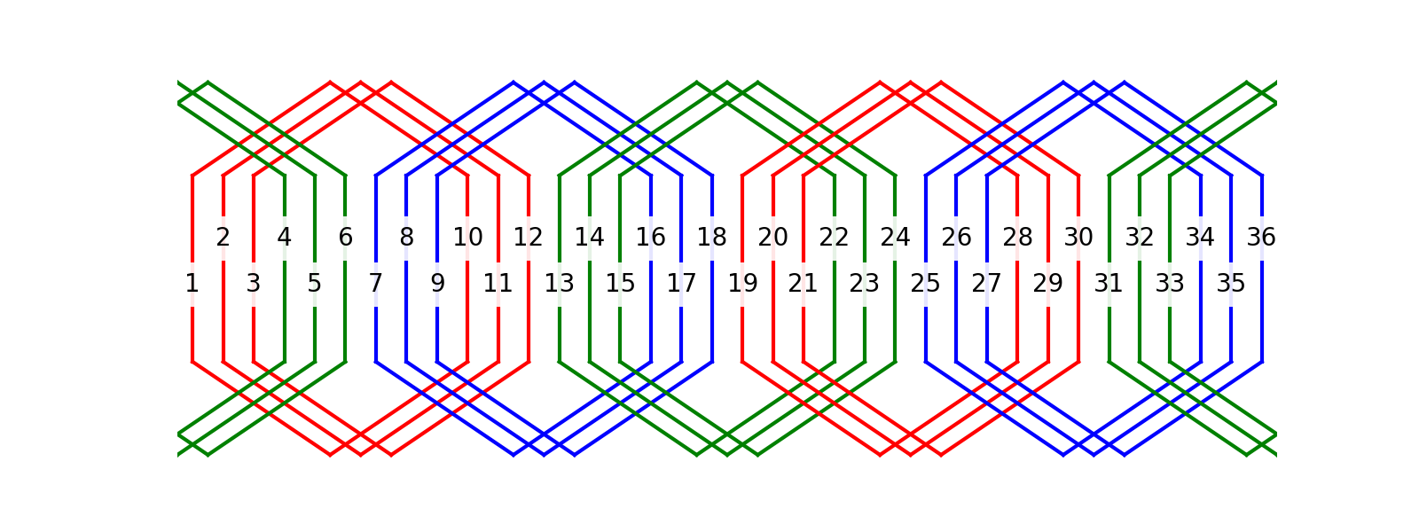
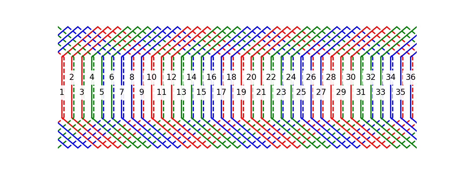
36槽4极单层绕组
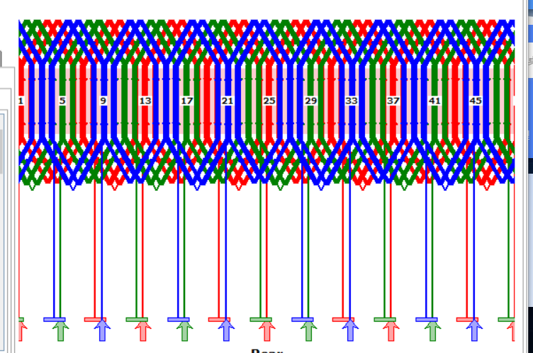
36槽4极整距双层绕组
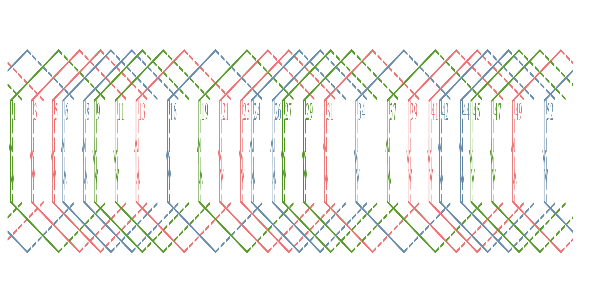
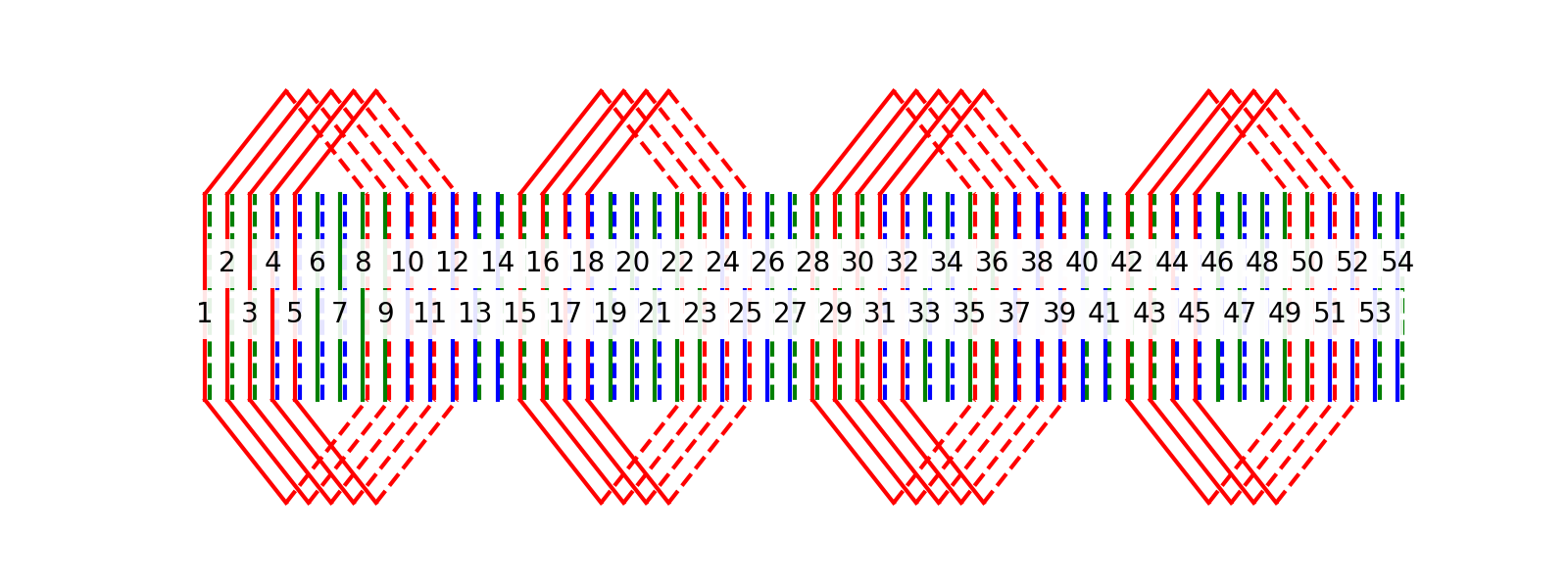
36槽4极短距(节距为7)双层绕组(只绘制A相)
线圈间连接和串并联支路等内容